A.C Through an Inductor
An inductor is an electrical component, typically a coil of wire, that opposes changes in the electric current passing through it. This section explores its behavior in an Alternating Current (A.C.) circuit.
Key Concepts
Inductor in an A.C. Circuit
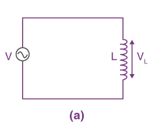
When an alternating voltage is applied across an ideal inductor (with zero resistance), the changing current induces a back e.m.f. (ε) that opposes the change. The applied voltage must be equal in magnitude to this back e.m.f. at every instant.
- Applied Voltage = Back e.m.f.
- Back e.m.f. formula:
ε=LΔtΔI
where L is the inductance.
Figure 20.11 (a): A.C through an Inductor.
Voltage and Current Phase Relationship
- Let the alternating current through the inductor be represented by:
I=I0sinωt
- The applied voltage V required to overcome the back e.m.f. is:
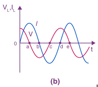
By comparing the equations for current and voltage, we conclude that in a purely inductive circuit, the voltage leads the current by 2π radians or 90∘.
Figure 20.11(b): Voltage leads the current by 90∘.
Inductive Reactance (XL)
- Definition: The opposition offered by an inductor to the flow of A.C. is called inductive reactance. It is analogous to resistance in Ohm's law.
- Formula: From the peak voltage equation V0=I0(ωL), we can define reactance X as:
or in terms of frequency ():
Summary
- An inductor opposes changes in current by inducing a back e.m.f.
- In a purely inductive A.C. circuit, the voltage across the inductor leads the current through it by a phase angle of 90∘ (π/2 radians).
- Inductive reactance (XL) is the measure of an inductor's opposition to A.C. and is measured in Ohms (Ω).
- Reactance increases linearly with both the inductance () and the A.C. frequency ().
Inductors are crucial components in circuits like filters, oscillators, and transformers, where controlling current based on frequency is essential.
References
(Derived from FBISE textbook)