20.4.1 A.C. Through a Resistor
This section describes the behavior of an alternating current (A.C.) circuit that contains only a resistor connected to an A.C. voltage source.
Key Concepts
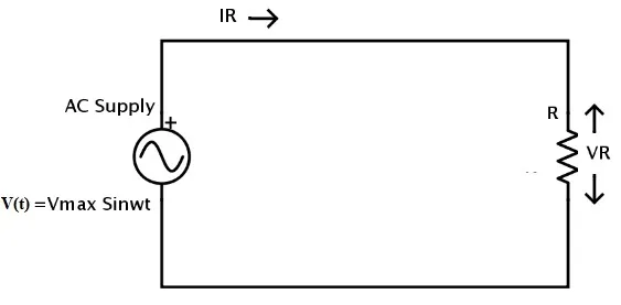
- Circuit Setup: A resistor with resistance R is connected across an alternating voltage source.
*Figure 20.10 (a): A.C through a resistor.*
-
Alternating Voltage: The instantaneous voltage provided by the source is given by:
V=V0sin(ωt)
where V0 is the peak (or maximum) value of the voltage and ω is the angular frequency.
-
Alternating Current: According to Ohm's Law (V=IR), the instantaneous current I flowing through the resistor can be found:
I=RV=
By defining the peak current as , the equation for the current becomes:
-
Phase Relationship:
- Comparing the equations for voltage (V=V0sin(ωt)) and current (I=I0), we can see that the sine function argument () is the same for both.
-
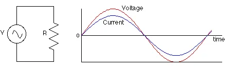
Waveform Representation:
The in-phase relationship between voltage and current is visualized below. Both waves are perfectly aligned.
*Figure 20.10 (b): Voltage and current are in phase.*
Summary
- When an A.C. voltage is applied across a resistor, the resulting current is also alternating and sinusoidal.
- Ohm's law (V=IR) applies to the instantaneous and peak values of voltage and current in the resistor.
- The most important characteristic of a purely resistive A.C. circuit is that the voltage across the resistor and the current through it are in phase.
References
(Derived from FBISE textbook)