RL Series AC Circuit
This section covers the behavior of alternating current (AC) in circuits containing capacitors and resistors, specifically focusing on RL and RC series configurations. It introduces the concepts of capacitive reactance and impedance.
Key Concepts
A.C Through a Capacitor
When an alternating voltage V=V0sinωt is applied across a capacitor, the charge on the capacitor at any instant is q=CV=CV0sinωt. The resulting current is the rate of change of charge:
I=ΔtΔq=CV0
where the peak current is I0=CV0ω.
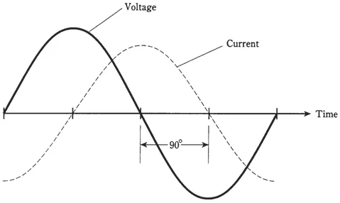
- Phase Relationship: In a purely capacitive AC circuit, the voltage lags the current by 2π radians or 90∘.
Figure 20.12 (b): Voltage lags the current by 90∘.
-
Phasor Diagram: The phasor diagram shows the voltage phasor 90∘ behind the current phasor.
-
Capacitive Reactance (XC): This is the opposition offered by a capacitor to the flow of AC. It is analogous to resistance.
X
Capacitive reactance is measured in Ohms () and is inversely proportional to the frequency () and capacitance (). For DC (), is infinite, meaning a capacitor blocks DC current.
Impedance (Z)
Impedance is the total opposition to the flow of alternating current in a circuit, combining the effects of resistance (R) and reactance (X). It is measured in Ohms (Ω).
RL Series AC Circuit
A circuit with a resistor (R) and an inductor (L) connected in series.
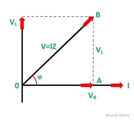
- The voltage drop across the resistor, VR=IR, is in phase with the current.
- The voltage drop across the inductor, VL=IX, leads the current by .
Figure 20.13 (b): Phasor diagram of RL series circuit.
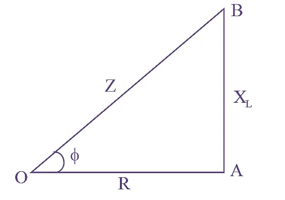
The total voltage V is the phasor sum of VR and VL. The impedance Z is calculated using the Pythagorean theorem:
where is the inductive reactance.
- Impedance Triangle: A right-angled triangle with sides R, XL, and Z.
Figure 20.13 (c): RL Series Impedance triangle.
RC Series AC Circuit
A circuit with a resistor (R) and a capacitor (C) connected in series.
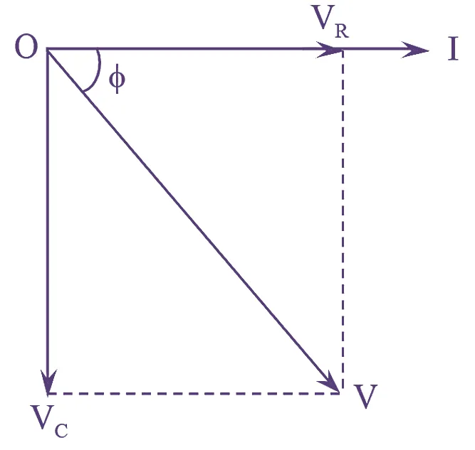
- The voltage drop across the resistor, VR=IR, is in phase with the current.
- The voltage drop across the capacitor, VC=IX, lags the current by .
Figure 20.14 (b): Phasor diagram of RC series circuit.
The total voltage V is the phasor sum of VR and VC. The impedance Z is:
where is the capacitive reactance.
Possible Questions/Answer
Summary
- In a pure capacitive AC circuit, the voltage lags the current by 90∘ (π/2).
- Capacitive reactance (XC) is the opposition to AC by a capacitor, inversely proportional to frequency and capacitance.
- In an RL series circuit, the voltage leads the current by an angle between and .
The analysis of impedance and phase relationships in RL and RC circuits is fundamental to designing and understanding filters, power supplies, and many other electronic systems.
References
(Derived from FBISE textbook)