Not started
Finding lessons...
Half-wave rectification is a process that converts an Alternating Current (AC) signal into a Direct Current (DC) signal. This is achieved by allowing one half-cycle of the AC waveform to pass through while blocking the other half-cycle.
A simple half-wave rectifier consists of a single diode (D) connected in series with a load resistance (R), as shown in the circuit diagram below.
Figure 20.3: Half-wave rectifier circuit.
The operation can be broken down into two phases corresponding to the AC input cycle:

*(a) Diode is forward-biased (closed switch)*
2. Negative Half-Cycle:
* The diode D is reverse-biased.
* It offers very high resistance, effectively acting as an open switch.
* No current (or negligible current) flows through the load resistor R. The output voltage is zero.
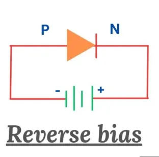
*(b) Diode is reverse-biased (open switch)*
The result of this process is that only the positive halves of the AC input waveform appear at the output. This creates a pulsating DC waveform.
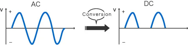
Figure 20.5: (a) AC input signal waveform, (b) Pulsating DC output signal waveform.
To convert this pulsating DC into a more constant DC, a filter (such as a capacitor) is used. The filter smooths out the pulses, providing a steadier DC output.
| AC Cycle | Diode Bias | Diode Resistance | Effective State | Output |
|---|---|---|---|---|
| Positive | Forward-biased | Very Low | Closed Switch | Current flows |
| Negative | Reverse-biased | Very High | Open Switch | No current |
(Derived from FBISE textbook)
